LED Beats
I was fortunate enough to get my hands on a Simonne Jones 8’x 2′ abstract oil painting on (very heavy) plywood. The painting is impressive in its non-illuminated state.

As she does with many of her paintings, she incorporated an (analog 12V) LED strip around the backside perimeter which, when lit, shifts the experience to a whole new branch of super (yeah, a Complex Analysis reference). Instead of attaching a store bought infrared LED controller, I got her blessing to build my own controller. Mind rocketed off. Immediately knew that I wanted to assemble a system where I could control the LEDs via the network. That was just the start…
All the hype and amazing things that have been built using the Raspberry Pi almost influenced me enough to get one of them for this project. Research kept me in check; way overkill for this project. I decided instead on an Arduino because of its flexibility, ease of use, massive community, availability, and price. I picked up
- + Arduino UNO R3 from SparkFun Electronics for $30.00
- + Arduino Ethernet shield from Beboxx $28 – Send commands somehow to the Arduino via network. WiFi shields are ridiculously priced at ~$90
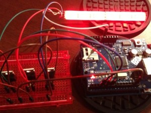
Also bought a breadboard, a few transistors, some jumper wires, a 12V power supply, did some LED soldering and assembled this unit to test with:
After installing the Arduino IDE and working through a few of the blinking LED examples, it was software architecture time. I had some experience working with Open Sound Control (OSC) from toying around with Visual Projection Tool (VPT) on a flight to Maui. No joke, priceless faces of seatmates as they watched scrolling numbers and objects shoot across and light up my screen; can only wonder what they thought was going on. VPT has a built in OSC server that can receive OSC commands to control the objects you create. Highly recommend this Open source software if you are looking for a visual projection tool. HC, its creator, is active in the Google forum and very helpful!
Now. An Arduino OSC library? No doubt. Stumbled upon Recotana’s ArdOSC library which is a very robust and easy to use library with great examples (only negative is its lack of documentation, but nothing little doxygen couldn’t slap a band-aid on). This library had all the features I was looking for
- + Arduino firmware 0022 support
- + 256 character addresses
- + up to 16 arguments
- + int32/float/string argument types
- + supports callback functions
Also ran into OSCuino which looks to be very flexible as well if you are looking for an alternative. Found my lib, time to peck…
Got My Code On
OSC Server + Arduino
#include

//server MAC address.  Default MAC used in example code
byte serverMac[] = { 0xDE, 0xAD, 0xBE, 0xEF, 0xFE, 0xED };
//assign an IP address
byte serverIp[]  = { 192, 168, x, x };
//assign a listening port
int  serverPort  = xxxx; //OSCserver listening port

//instantiate OSCServer and OSCMessage classes
OSCServer server;
OSCMessage *_msg;

//define which pins the LED leads will be connected to
int redPin = 5;
int greenPin = 6;
int bluePin = 3;
Callback Functions
//Arduino setup loop
void setup(){
 //initiate serial port with baud rate 19200. Used for debugging with Arduino's serial monitor
 Serial.begin(19200);
 //begin ethernet server
 Ethernet.begin(serverMac ,serverIp);
//initiate OSC server
 server.begin(serverPort);

 //create callback functions. When an OSC message with address "/ard/red" is sent to the server, it will run the function "red"
 server.addCallback("/ard/red",&red);
 ...
 ...
}
Perk Arduinos’ Ears for Incoming Messages
void loop(){
  if(server.aviableCheck()>0){
  //  Serial.println("alive! ");
  }
}
Functions for them Callbacks
//create "red" function. Use analogWrite to turn red LED to the value sent in the OSC message
void red(OSCMessage *msg){
  //get the first value in the OSC message.  Message is sent as a float
  //value then converted to int (thanks to TouchOSC)
  int rVal = (int) msg->getArgFloat(0);
  //write value to redPin
  analogWrite(redPin,rVal);
}
The Arduino OSC server can now manipulate all the red LEDs on the strip when it receives messages like:
- + /ard/red 0 (red LED off) or this
- + /ard/red 127 (red LED half on)
- + /ard/red 255 (red LED on)
Similarly, to control the green and blue LEDs, you would create “green” and “blue” callbacks and their associated functions. From here the possibilities are unlimited for lighting schemes. As an example this simple function generates 3 random values between 0 and 255 and assigns one to each R, G, and B to create a random color on the LED strip when it receives the message /ard/prog 2 :
//callback function with custom lighting programs (prog)
server.addCallback("/ard/prog",&prog);

...
//Give each custom program a number in the if/else statement and define what to do with the LEDs
void prog(OSCMessage *mes){
  int progNum = (int)mes->getArgFloat(0);
  if (progNum == 1) {
      ...
      ...
  }
  else if (progNum == 2) {
    int r = random(0,255);
    int g = random(0,255);
    int b = random(0,255);
    analogWrite(redPin,r);
    analogWrite(greenPin,g);
    analogWrite(bluePin,b);
Make it Move!
The OSC server is running on the Arduino and is ready to do what it is told. There are numerous ways to send OSC messages. I was interested in methods for manipulating the LEDs via PERL, Processing, iPhone (think “painting LED remote controller”), and Ableton Live.
PERL
PERL was ideal to create a simple test client. It has a simple OSC server and client libraries called Net::OpenSoundControl::Server and Net::OpenSoundControl::Client. I only needed the client library since I was only interested in sending commands to the Arduino and didn’t care about receiving any messages back. Installed the PERL libraries and wrote this simple test client to send red LED on/off commands 5,000 times
#!C:xamppperlbinperl.exe
#
use lib 'C:xamppperllib';
use Net::OpenSoundControl::Client;

my $port = '';
# Check for both OSC server IP and OSC port from the command line arguments
if (@ARGV != 2) {
	print "ntusage: perl sendOSC.pl  <port#>nn";
	exit;
} else {
	$server_ip = $ARGV[0];
	$port = $ARGV[1];
}
//instantiate Client object using the passed IP and port
my $client = Net::OpenSoundControl::Client->new(
		Host => $server_ip, Port => $port)
		or die "could not start client: $@n";

#Send 10,000 test OSC messages to turn red LED on/off.  Arduino is expecting
#float values so must send them as such
my $mesgVal = 0.0; #off
for (1..10000) {
	if ($mesgVal == 0.0 ) {
		$mesgVal = 255.0;
	    } else {
		$mesgVal = 0.0;
	    }
	    $mesg = "/ard/red";
	$client->send(["$mesg" ,'i', $mesgVal]);
	print $mesgVal . "n";
	sleep(1);
}
Worked like a champ.
iPhone Control
TouchOSC is a great phone app (iPhone $4.99) with which you can build OSC and Midi based interfaces using the TouchOSC Editor (available from the downloads page of the main TouchOSC site). With the interface, you can send OSC commands to any server on your local network with the push, twist or slide of some buttons. Steps to use are simple.
- + Install iPhone app
- + Configure the app to point to the OSC server running on the Arduino
- + Build an interface using the TouchOSC editor
- + Use
Built this simple interface to control the R, G, and B LEDs: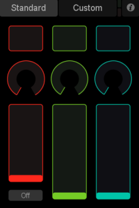
TouchOSC editor has outstanding documentation. As a simple illustration, the red button (toggle button type in TouchOSC) in this interface has the following options:

When the toggle button is pressed it will send the OSC message
/ard/red 255
to turn the red LEDs on and when toggled off will send
/ard/red 0
and turn the red LEDs off. The controls for the fader and rotary controls work similarly. My iPhone is now officially an LED remote control.
Processing
The end goal of this project was to get the painting to move to a beat. Processing was ideal for this since it interfaces well with Arduino using both serial, which is good for testing since you can upload sketches and use the serial monitor to print out OSC commands being sent to it, and the OSC client/server Processing library oscP5. Here’s a sample OSC test client using the oscP5 library to turn the red LEDs on/off:
import oscP5.*;
import netP5.*;

OscP5 oscP5;
NetAddress arduinoAddress;

int flag = 0;

void setup(){
  size(50, 50);
  //this is very important when sending OSC commands in rapid
  //succession
  frameRate(25);
  //create listening server on port 10000. Can be used to send OSC
  //messages to Processing
  oscP5 = new OscP5(this,10000);
  //specify the location of the OSC server on the Arduino
  //server IP, port
  arduinoAddress = new NetAddress("192.168.x.x",xxxx);
}

void draw (){
  //construct OSC message for red LED
  OscMessage pinMsg = new OscMessage("/ard/red");
  //send 0.0 or 255.0 (off/on). Again note that I am sending float values
  //which are converted to int on the Arduino side
  if (flag == 0) {
    pinMsg.add(255.0);
    flag = 1;
  } else {
    pinMsg.add(0.0);
    flag = 0;
  }
  //output OSC message to Processing console
  println(pinMsg.addrPattern());
  println("----------------");
  //send OSC message to Arduino server
  oscP5.send(pinMsg, arduinoAddress);
}
Success activating the LEDs via OSC and Processing.
Idea was to build an audio player (a bootleg iTunes) which would detect various beats in an audio file and activate the R, G, and B LEDs by sending OSC commands to the Arduino. Naturally, I needed to find a way to detect beats in an audio file. Processing has a sound library called Minim which had every method I needed:
- + Playback capabilities
- + Metadata output
- + Ability to detect different types of beats
Using Minim, oscP5, and pieces of the Revolution – MP3 Player OpenProcessing sketch, this code creates a simple MP3 player that will play an audio file, detect bass, snare, and hi hat beats, then send OSC commands to the Arduino to activate/deactivate the R, G, B LEDs respectively:
import ddf.minim.*;
import ddf.minim.analysis.*;
import processing.serial.*;
import cc.arduino.*;
import oscP5.*;
import netP5.*;

OscP5 oscP5;
NetAddress arduinoAddress;
Minim minim;
AudioPlayer song;
AudioOutput out;
BeatDetect beat;
BeatListener bl;
Arduino arduino;
PFont font;
PImage bg;
color oscillatorColor = color(0,0,0);

void setup()
{
  //size of the player
  size(367, 550, P3D);
  //this is very important when sending high volume of OSC commands, trust me, I learned the hard way.  I began
  //with a frame rate of about 60 and experienced painful delays as the amount of commands at 60fps was
  //inundating the server.
  frameRate(25);
  String oscillatorColor = "";
  //background image and font
  bg = loadImage("../data/bgPic.jpg");
  font = loadFont("../data/Consolas-48.vlw");

  //instantiate minim object
  minim = new Minim(this);
  out = minim.getLineOut();
  song = minim.loadFile("PATH_TO_YOUR_AUDIO_FILE");
 //create beat detection object
 beat = new BeatDetect(song.bufferSize(), song.sampleRate());
 beat.setSensitivity(10);
  // make a new beat listener, so that we won't miss any buffers for the analysis
  bl = new BeatListener(beat, song);

  //instantiate OSC object for listening server on port 10000. Receive messages from outside sources to control
  //Processing
  oscP5 = new OscP5(this,10000);
  //location of Arduino OSC server
  arduinoAddress = new NetAddress("",);
}

void draw()
{
  background(0);
  image(bg,0,0);
  fill(255,0,0);
  //stop/pause button
  noStroke();
  rect(30, 500, 20, 20);
  textFont(font, 15);
  fill(100, 255, 0);
  //Print Artist/SongName to top of window
  text(song.getMetaData().author() + " - " + song.getMetaData().title(), 40, 40);

  //Construct OSC Message object.  Callback function on Arduino side called "player"
  OscMessage pinMsg = new OscMessage("/ard/player");
  //check the type of beat that is detected and send OSC message with a value of 1, 2, or 3
  if ( beat.isKick() ) {
    println("kick");
    oscillatorColor = color(255,0,0);
    //append 1 to OSC message, red LED
    pinMsg.add(1);
  }
  else if ( beat.isSnare() ) {
    println("snare");
    oscillatorColor = color(0,255,0);
    //append 2 to OSC message, green LED
    pinMsg.add(2);
  }
  else if ( beat.isHat() ) {
    println("hat");
    oscillatorColor = color(0,0,255);
    //append 3 to OSC message, blue LED
    pinMsg.add(3);
  } else {
   //send OSC message - all Off
    pinMsg.add(100);
  }
  //send the OSC message to arduino
  oscP5.send(pinMsg, arduinoAddress);
  //draw oscillator.  Color of oscillator will turn R, G, B, depending on beat detected
  for(int i = 0; i < out.bufferSize() - 1; i++) { stroke(oscillatorColor); line(i, 310 + song.mix.get(i)*250, i+1, 310 + song.mix.get(i+1)*250); } } //Control play/pause button void mousePressed() { if(mouseX>30 && mouseX<50){ //co-ordinates for button area if(mouseY>500 && mouseY<520){
      if (song.isPlaying()){  //button function, ie play/pause
        song.pause();
      }
    else{
      song.play();
    }
}
//stop the song that is playing
void stop()
{
  // always close Minim audio classes when you are finished with them
  song.close();
  // always stop Minim before exiting
  minim.stop();
  // this closes the sketch
  super.stop();
}
The output of this sketch isn’t all that exciting. A box with a play/pause button in it, and an oscillator that changes color according to the beat that is detected.
Ableton Live
Getting up on my Ableton Live game and this will be happening at some point. Ableton beats triggering the LEDs. Stay tuned…
Mount it up Where?!
Yup pretty much. That’s what it felt like. When you have to mount an 8’x 2′ 60 lb anything 15′ up, solo nonetheless, it’s no easy task. Toughest part of this whole project. This is where it had to go:
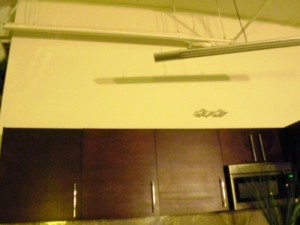
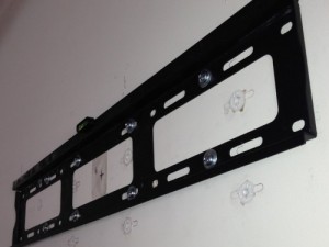
A flatscreen TV mount was the only feasible way to mount this thing. Note. walmart.com prices != Walmart In-store prices. I found a cheap TV mount on walmart.com for $19.98. Same mount was over $100 in the store. No joke. Needless to say I waited for the slow slow shipping.
Drywall is no Match
If you ever need to mount something very heavy onto drywall with no studs, look no further than these beasts:

They are rated to support up to 110 lbs a pop in drywall! (sin studs, statics at it’s finest). Paranoia means you buy 8. Screwing up the first time means you buy 16:
Uh no. That was not my best work.
Working out that Backside
Gorilla glue, 4×3/4″ plywood risers (space between the wall and painting), various sizes of drywall screws, TV mounting brackets, the clip from an old clipboard (so I can pull the controller off to program as needed), the electronics, some LED testing and it’s prepped proper for hanging:


Probably not the smartest thing to try and mount on my own, but after about half hour of heavy lifting and straining I got it up onto the mount, tightened the safety bolts, and connected the network cable and power supply, it was in its final resting place.
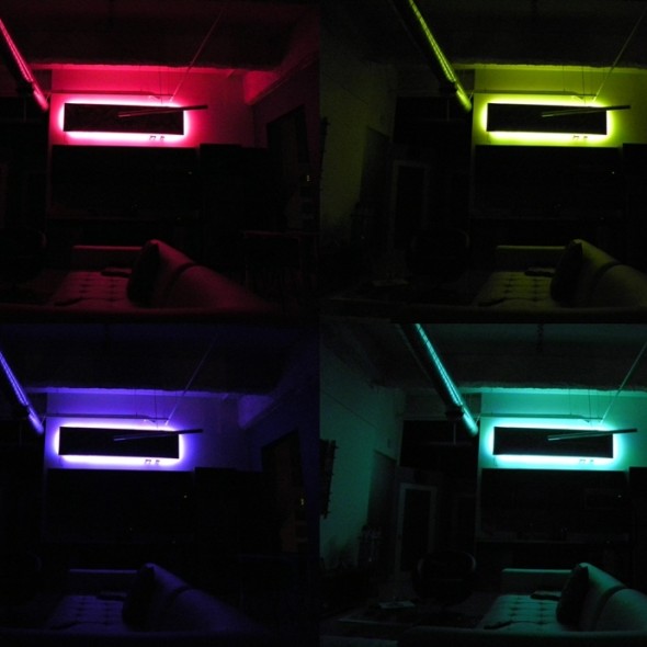
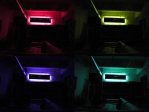
First Night Out
Lights off. Four of the numerous color/brightness states this piece could be in (an n^r permutation says 16,777,216 to be exact) it morphs into an entire new work of art. Dark and light produce two very different, yet equally as pleasing experiences. Needless to say I am kinda of fan of what it does to my space!
Skip the Tech and see it in Action!
Pinnacle. Audio file triggering red, green, or blue LEDs when Processing detects bass, snare, or hiHat respectively. Unfortunately I can’t share the song it was meant to play to, so you’ll have to settle for one of mine…Red Sky at Night; fitting title for the bass heavy, i.e. red heavy, beats! Cut me some slack with the audio and video quality. iPhone recording was actually better than my POS Nikon camera.
Play hard, learn harder. On to the next…